For other 5.1 deep dives:
- vSAN ESA
- Distributed Virtual Port Group Separation for Management Domain Appliances
- Custom Edge Cluster Deployments
Ever since we implement multi-pnic support back in VCF 3.9.1, customers have asked for an easier method to deploy clusters with >2 NICs and multiple distributed switches.
Up until VCF 5.1, if the user wanted something else than 2 NICs (that had to be vmnic0/vmnic1!) and 1 VDS, they have been forced to use the API to deploy workload domains/clusters and when expanding these clusters. My VCF JSON Generator certainly helped a great deal, but this feature should have been in the SDDC Manager UI!
Well, guess what? VCF 5.1 adds this capability!
We can now create multi pNIC, multi VDS deployments using the UI. We can set the VDS name, control the vmnic to VDS uplink mapping and even set the active/standby uplink configuration.
So how does this look in the UI?
It doesn’t matter if you want to create a new cluster or a new VI WLD. The VDS configuration is defined on a per cluster basis!
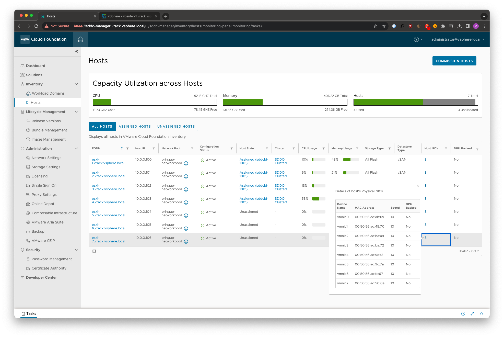
From the Hosts menu, the number of host NICs are now visible.
Let’s go ahead and create a new cluster, in the UI!
Provide the storage type, name of the cluster, which hosts to use etc
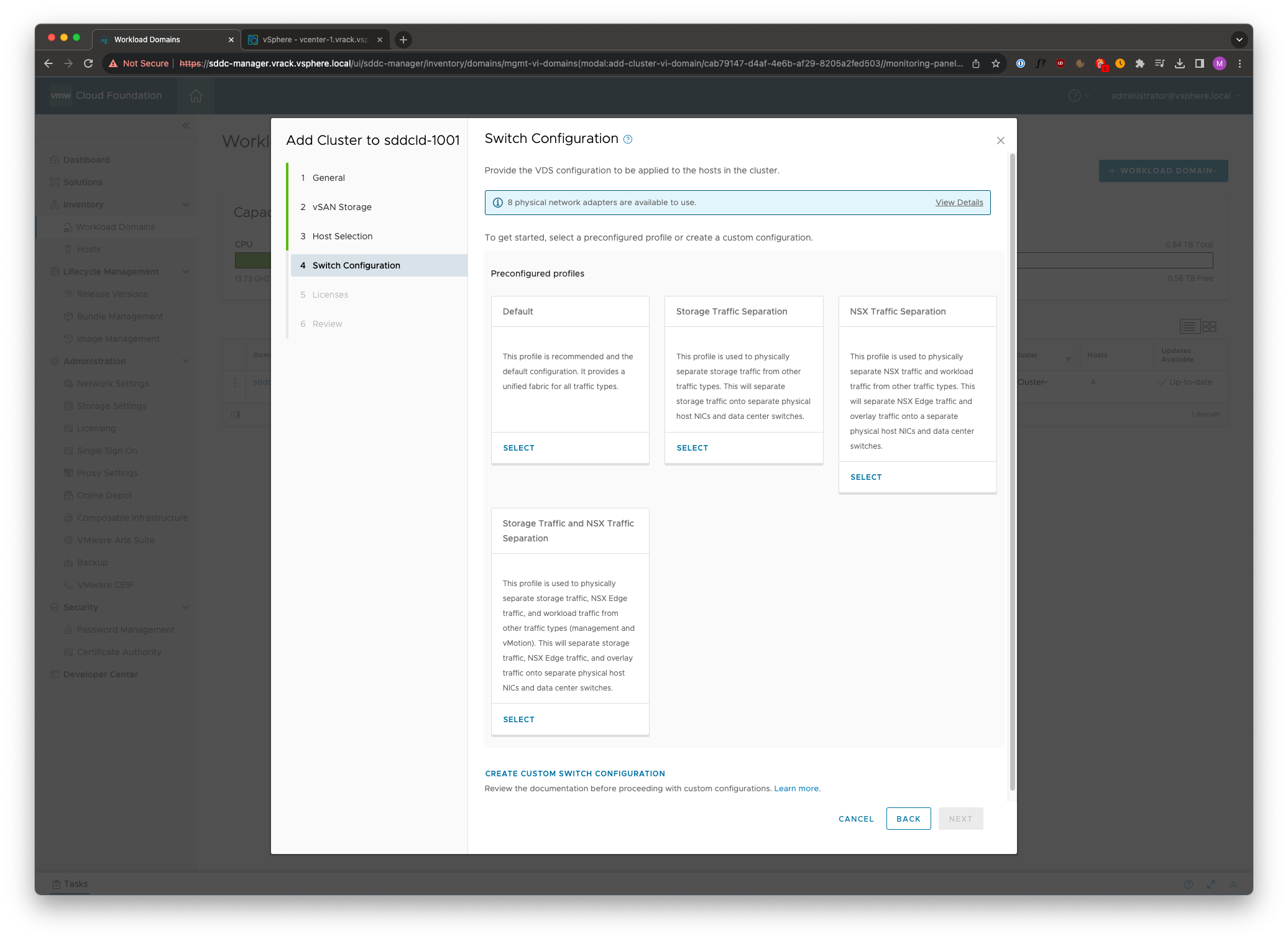
On the Switch Configuration page, we first see that we have 8 physical NICs available.
There are 4 preconfigured VDS profiles:
- Default – This is a single VDS with all uplinks attached.
- Storage Traffic Separation – This will create two VDS, first VDS will host Management, vMotion and NSX, the second VDS will host vSAN traffic
- NSX Traffic Separation – Again, two VDS, first VDS will host Management, vMotion and vSAN, second VDS will host NSX traffic
- Storage Traffic and NSX Traffic Separation – This will create three VDS, first VDS will host Management and vMotion, second VDS will host vSAN and third VDS will host NSX traffic
But, we also have a fifth option! Create Custom Switch Configuration
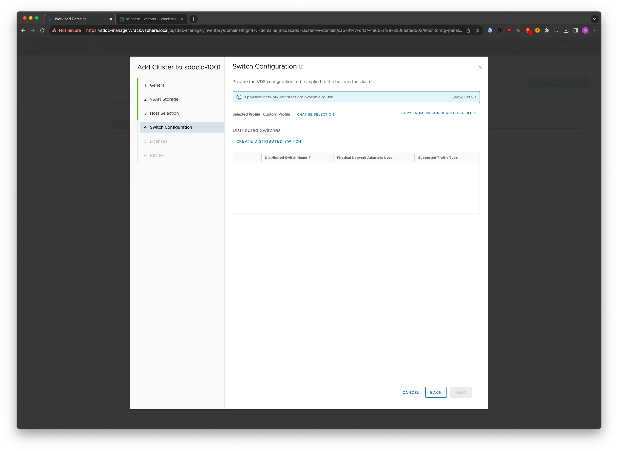
Let’s take a look at Create Custom Switch Configuration
Here we can copy the configuration of one of the preconfigured profiles, or create a new VDS layout altogether.
Let’s go ahead and create a custom configuration. We start with clicking Create Distributed Switch
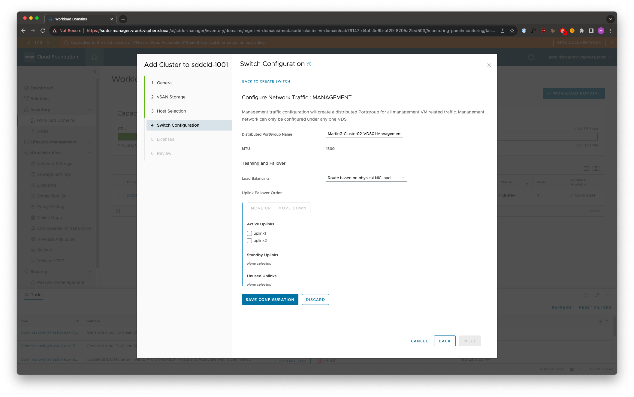
We are presented with the option of giving the VDS a name, set the MTU, define how many Uplinks.
Let’s create a VDS that will host the Management and vMotion traffic using 2 uplinks.
For each traffic type that you define, you have full configuration possibilities. You supply the name of the portgroup, the teaming/failover policy and you have the ability to control which uplinks should be active, standby or unused.
When it comes to the NSX configuration, we’re presented with more options than we previously had.
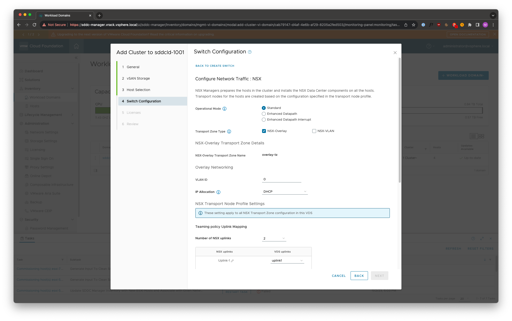
We can now configure Enhanced Datapath – DPDK.
We also have the option to configure the Transport Zones, we can choose to not create an Overlay TZ, or a VLAN TZ, but we must have at least one TZ configured.
In this case I’m going to create only an Overlay TZ on this VDS, I’ll create the VLAN TZ on another VDS.
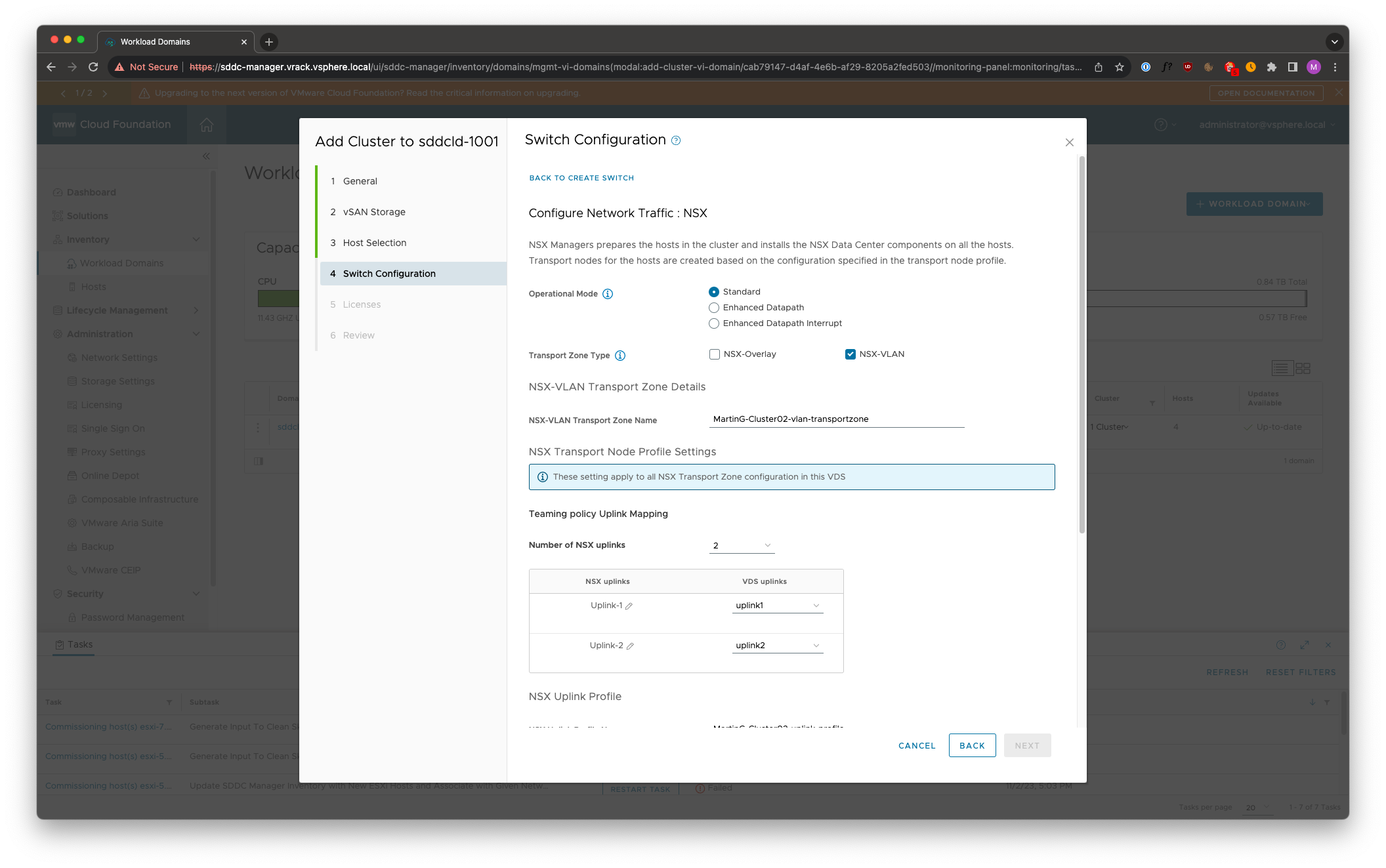
I don’t have the option to name the Overlay TZ, but I can name the VLAN TZ.
We also have the capability to define the Uplink mapping, uplink profile name and Teaming Policy (Failover Order, Load Balance Source, Load Balance Source MAC Address)
Creating another VDS for the VLAN TZ
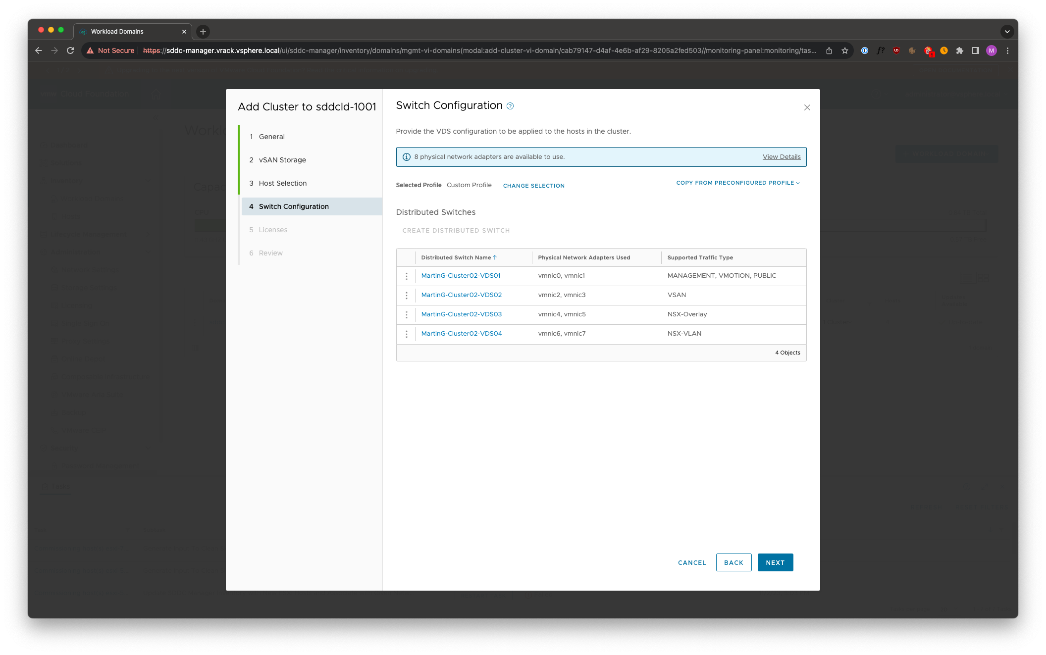
The end result look like this, four Virtual Distributed Switches
- VDS01 – Management, vMotion, PUBLIC – Public you ask? Public means it’s not carrying any of the predefined traffic types (Management, vMotion, vSAN, NSX). This can be used to create an empty VDS – which can be used for backup traffic for example
- VDS02 – VSAN
- VDS03 – NSX Overlay
- VDS04 – NSX VLAN
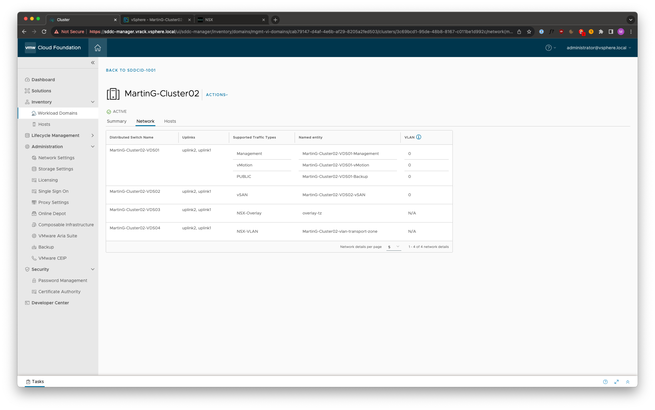
Once the cluster has been deployed, we can see the VDS layout in vSphere Client as well as in SDDC Manager
Leave a Reply